R & R Communications, Inc.
302-475-1351
TRAM PICTURES
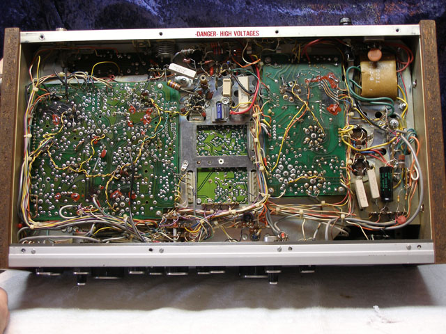
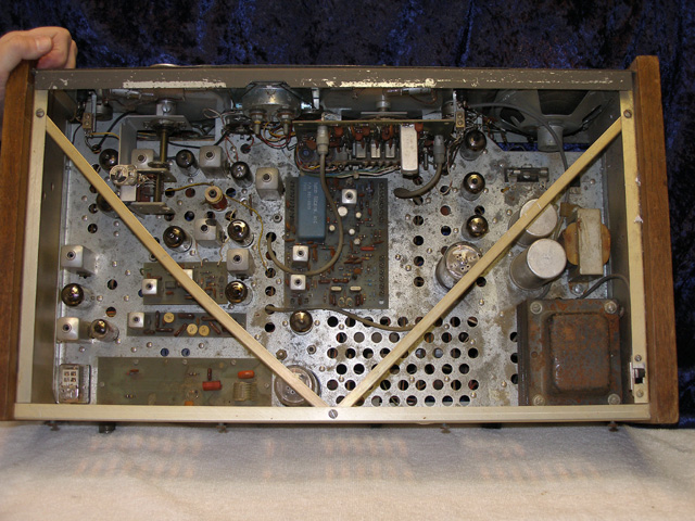
Tram D201A First Version
The PC Board To The Left Is The Receiver Board, The PC Board In The
Center Is The Balanced Modulator Board
The Board To The Right Is The Audio/Modulation/Voltage Board.
Notice The Discoloration From Heat On The Receiver Board And The
Red Glyptol (Hi Arc Compound) On The Highly Burnt Areas.
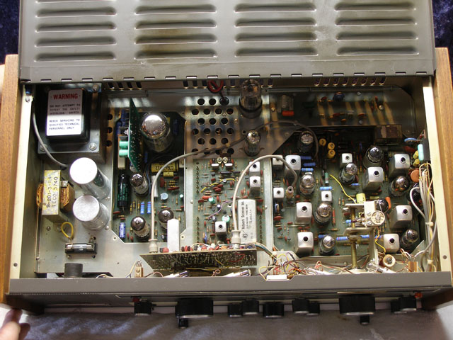
Tram D201 Second Version
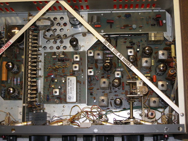
Notice The 23 Channel Crystal Board In The Front. Also Notice
The Vertical BA Board Between The Power
Transformer And The 6L6 Audio/Modulation Tube.
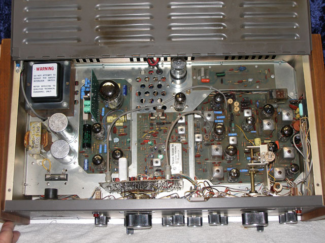
Tram D201 Second Version After Rebuild.
Notice The Blue Flameproof High Wattage Resistors. All
Of These Resistors Are 1 Inch Off The Board.
Also Notice 2 The Electrolytic Filter Capacitors To The Left And
In Front Of The Power Transformer.
Notice The Discoloration From Heat On The Inside Cover .
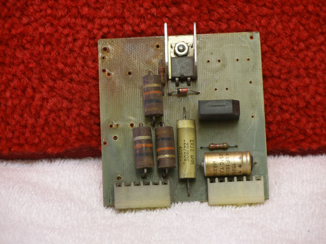
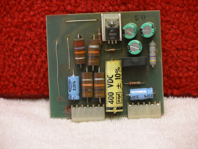
BA Board In The Tram D201. (Partially Assembled)
Notice The Heat Discoloration In The Upper Left Corner
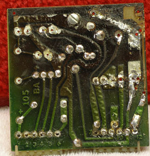
BA Board In The Tram D201
Notice The Black Discoloration On The Board
And The Melted Solder Joints.
 BA
Board In The Tram D201A Second Version.
BA
Board In The Tram D201A Second Version.
 BA
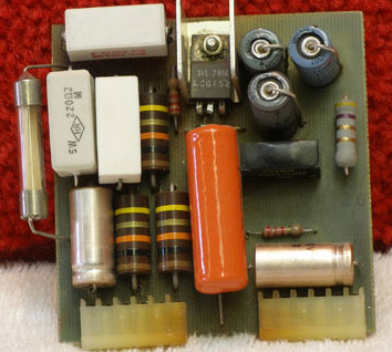
Board Rebuilt For The Tram D201 Second Version
BA
Board Rebuilt For The Tram D201 Second Version
 Second
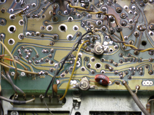
Version Of The Tram D201A With Copper Color Torroid Transformer.
Second
Version Of The Tram D201A With Copper Color Torroid Transformer.
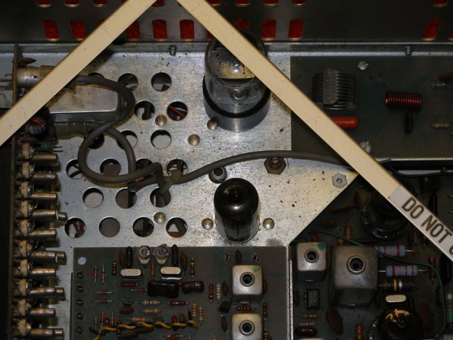
Tram D201A Both Versions. Notice The Driver Tube a 12BY7 And
To The Rear The RF Final Tube A 6DG6.
Tram D201's Used A 6L6 Final Tube.
Tram D201A Second Version.
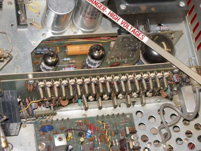
Notice The 40 Channel Crystal Board With 23 Crystals. 18-16MHZ
& 4-4MHZ Crystals.
Also Notice The Channel Selector. This One Will Fail At Some
Point In Time. There Is No
Replacement.
Tram D201A Both Versions. Another Angle Of The Crystal Board
And Channel Selector.
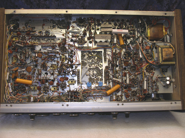
Tram D201 First Version (Hand Wired)
Tram D201 First Version (HAnd Wired)
